DIY Scratch Plate
A scratch plate, aka pickguard, is the piece of plastic on the face of the guitar, whose main function is to protect the finish of the instrument from getting scratched up when the guitar is played.
On many electric guitars it also serves as the cover for the controls and sometimes mounting for the pickups.
With the right tools and skill set, a pickguard is not difficult to make.
Template
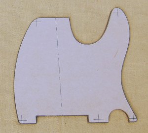 Scratch plate template for a Telecaster-type guitar
First you need a template. Mine are drawn up in CAD and printed out on regular office paper, and glued to 3/16" hardboard. I typically try and incorporate fastener locations. The hardboard is trimmed to the contour line. The edge needs to be smooth, i.e. no bumps.
I purposely leave out pickup cavities and neck pocket. That's just how I roll.
Setting Up
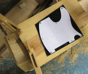 Setup for routing pickguard
Here I have drilled all the mounting holes and added countersunk holes for four of the mounting screws located closest to the four corners. I countersink the holes in the template deep enough for the oval head screws to be buried below the face of the template so the router base can pass over without being scratched.
A piece of pickguard material has been cut out from a large sheet and sandwiched between the template and a piece of 1x8 pine board. It's all held together with the four countersunk screws and ready for the router.
The 1x8 is clamped to a solid base to stay put while working the router.
Router Bit
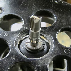 Stewart McDonald pattern bit
The router bit I use is pattern bit I got from Stewart McDonald (item number 0583). The bit is 3/8" diameter with a cutting depth of 1/2". I have added extra follower bearings that I purchased off ebay a lot cheaper than Stewmac wants for the same bearings.
Before starting it is important to adjust the cutting height so the bearing closest to the cutting tool rides on the template.
Cutting the Scratch Plate
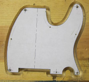 Pickguard contour routed
Follow the template with the bit. Notice the entry channel at the lower edge of the 1x8 in the picture. It's important to keep the router moving and not let it dwell in one place as it will cause burns. I usually retrace the entire template a couple of times in case the bearing lost contact against the template along the way.
Cleaning Up
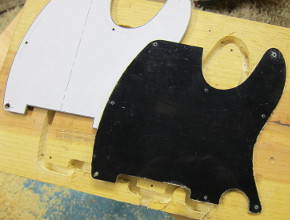 Pickguard ready for cleanup
At this point the template and pickguard can be removed from the board. With a scraper I bevel the edge by hand, and by eye to about 45 degrees. Now is also a good time to countersink the screw holes in the pickguard.
Transfer Mounting Holes to the Guitar
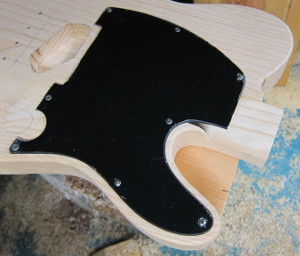 Preparing for routing neck pocket clearance
Lay the pickguard onto the guitar and line it up straight. It helps to temporarily mount other hardware. In the Telecaster example, I mounted the bridge with two screws and laid out the control cover to line everything up.
When you're happy with the location, take a pencil and transfer the mounting screw holes to the top of the guitar. Use a drill-press and drill the guitar body for the mounting screws.
Transferring the Neck Pocket Route
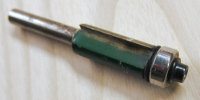 Edge trim router bit
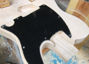
The neck pocket route on the guitar is transferred to the scratch plate using a 1/2" edge trim bit in the router. Adjust the height so the screw head at the bottom clears the guitar body.
|
The screws used for pickguards are typically oval heads, which when mounted correctly stands slightly proud of the scratch plate. As to not ruin the base plate on my router, I remove any screws that would interfere with the router base. One option is to temporarily replace the oval heads with regular flat heads during this step. Trim away... |
 Pickup route next Pickup route next |
Routing for the neck pickup
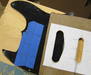 Pickguard marked with pickup location. Pickup router template laid on top.
Take the pickguard off the guitar again for this step.
Place blue masking tape on the pickguard at the pickup location and mark the centerline. Next I draw two lines perpendicular to the centerline, representing the front and back of the pickup.
Before I proceed with the router, I drill a hole in the pickguard with a 3/8" Forstner bit to become a staring point when routing. I'm not terribly excited about running my router bits through blue tape and I'm working on a better way, but for now this works well enough.
The hoes for the pickup height adjustment screws are transferred from the pickup onto the pickguard.
The finished Scratch Plate
Here it is. It many take a few hours, but not rocket science.
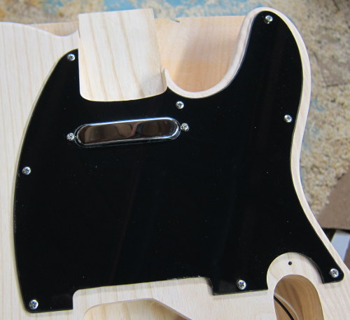 The finished Telecaster pickguard
Recent Articles
-
Speaker Plans
Feb 04, 18 05:23 PM
Speaker plans for download - free pdfs for DIY builders and tire kickers
